Miscellaneous photos of operations on the engine cases
These are some photos that haven’t been shared of some of the operations done on the engine cases.
The engine cases are jigged up on an angle block so we can mill the motor mount flat and level. Some weld had been added by previous owner to fill in depressions from the cases wobbling from loose motor mount bolts
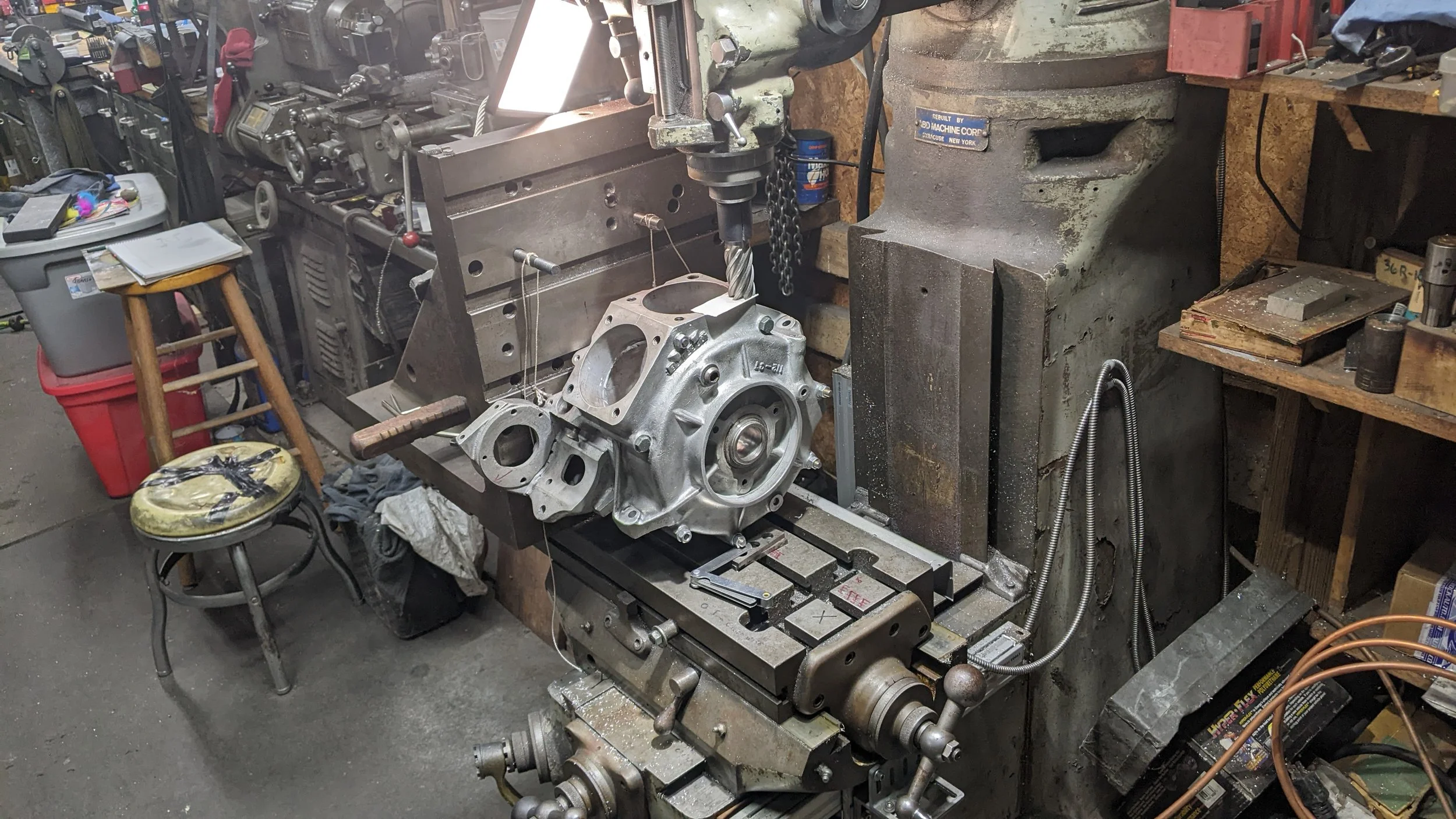
Checking plumb level of rear cylinder deck with milling tool and cigarette paper. Turns out that remarkably having machined by HD in 1938, they are still plumb 87 years later! Only required a little dressing up with a file on a couple of burrs.
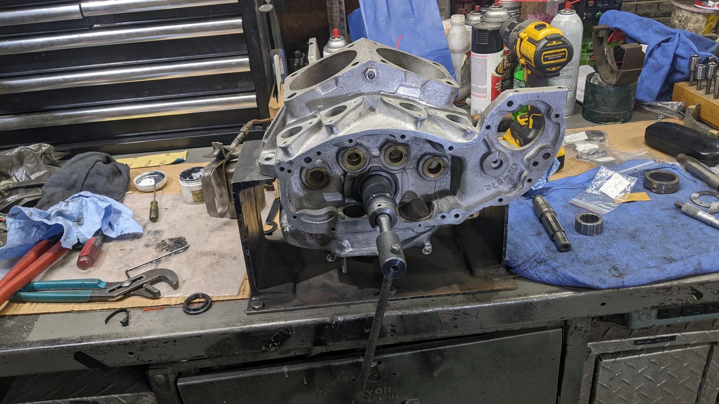
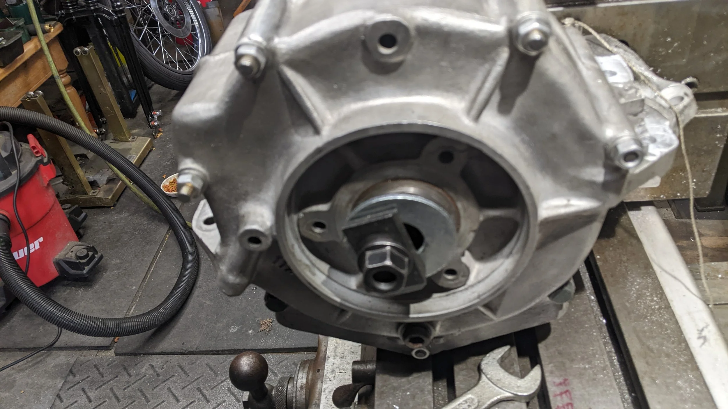
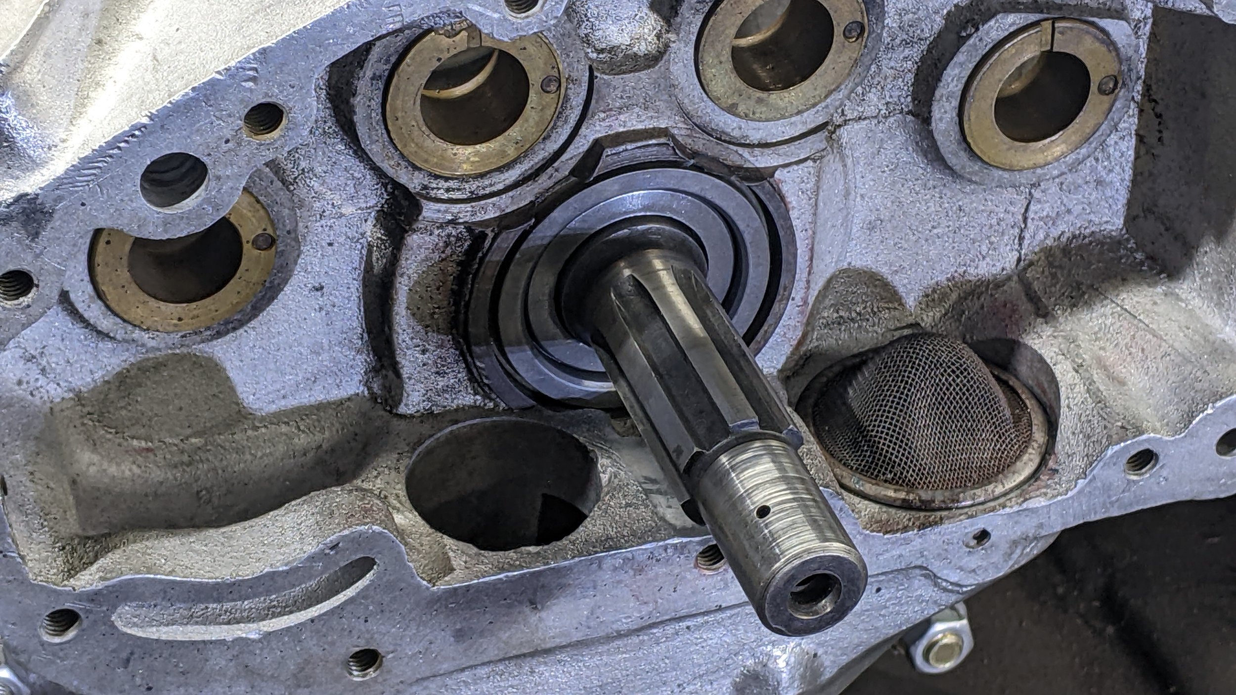
Lapping the pinion shaft bearing bush
Early HD cases from the late 30”s had blind mounting holes for the shaft bearings on the sprocket and pinion shafts. This was later changed so that they could be lapped in the field. It is possible to retrofit earlier cases such as these with the later bearing bushings and perform line lapping. It requires machining to the cases to fit the later bushes, but a necessity to obtain a proper bearing fit.
fitting the pinion shaft for proper bearing size
The procedure to check bearing fitment is to lap the bearing race in the case so that the actual shaft being used on the flywheel ass’y is used to test fit. A “plug” fit is first obtained that being a fit where the shaft will just slide through the bearing ass’y, and would fall through the bearing under it’s own weight. Then the rollers used in the test fit are measured and the 1/2 the desired fitted clearance (about one thousandth) is subtracted from the plug fit roller size and that smaller size roller is used in the final ass’y to assure proper running clearance. All parts must be dry,(no oil on them) so as not to upset your calculations