Dec24th 42UL update, Catching up with some pictures
Just trying to bring the build up to date, so I’m downloading some pics that were on the camera. We’ve hit a big SNAFU with the build in that it turns out the rear cylinder has a significant crack which has brought things to a halt for the moment. But, here are some positive progress pics:

Right wheel with connecting rods and crank pin. Take note of the message to posterity as to how the engine was balanced. Remarkably, Sharpie stands up to hot oil quite well. The row of prick punches were planned spots to drill the wheel for balancing purposes. Only used one slightly, as you can see.
Here’s the right wheel, (timing side) with rods assembled. Sorry, no pics of honing the rods to fit the crank pin. We updated the engine with T&O Torque monsters, and that necessitated updating the crankpin the the non stepped rod OHV motors use. The Motor had been redone in the not too distant past, but with the new pin, it was wise to slightly dress the rod races for proper clearance. Just a few passes on the Sunnen Hone. I have a friend who has the Sunnen setup and graciously lets me use it when needed.
Wheels clamped in alignment jig

Another view of wheels in the jig
Here the wheels are held in alignment so that the crank pin nuts can be tightened. This simple jig will usually get the wheels within +/- .002 thou. A good place to start.

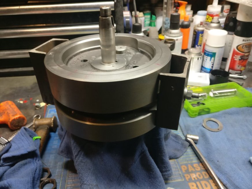
Flywheel ass’y in genuine surplus WW2 HD truing stand. Bought it from a retiring BSA dealer :-)
Here are the wheels waiting to be squeezed, teased and beaten into submission. In this case, the timing wheel was spot on and the sprocket wheel was 2 thou out. We chased it around a little with the Hammer and big “C” clamp and 15 minutes, we had it. ( sorry, no pictures of the squeezing and beating, This is a family site and we don’t show any pictures of parts abuse!)
Next up are pics of the case mainshaft bushes being lapped.

Drive side case busing setup

another view

Hand power here, don’t want to go too fast
We didn’t have to do much to size the races for this motor, it didn’t have too many miles on it since it had been redone, but I’m guessing that only oversize bearings had been installed, and the races not line lapped. There was no trace of honing marks on the bushes, and the drive side bush was tapered. There are 2 sets of 1/4” rollers on the drive side, and one set was fitted with insufficient clearance. No damage had been done, but by making a few passes with the lap, I was able to make the bush a uniform size and establish the proper clearances. The timing side was in good shape and properly sized, so I left it alone.
MOVING RIGHT ALONG, THE BIG CRACK….

THE CRACK

Another view

Complete wrap
This is the crack we discovered when the jugs were returned from receiving a ceramic coating in the combustion chamber. I had blasted the jug before sending off, and apparently when the jugs were baked, the oil oozed out of the crack as you see here. It’s the rear jug and the left rear mounting ear. Looking for a replacement as we speak. Some leads, but nothing concrete as yet. Never saw this while I was cleaning and blasting. Would not like to think what would have happened if I hadn’t caught it. Ugh!
That’s it for now. Merry Christmas, To be continued….